
Swapping out smart cart old T1 Adapter Board
Viewing this guide for
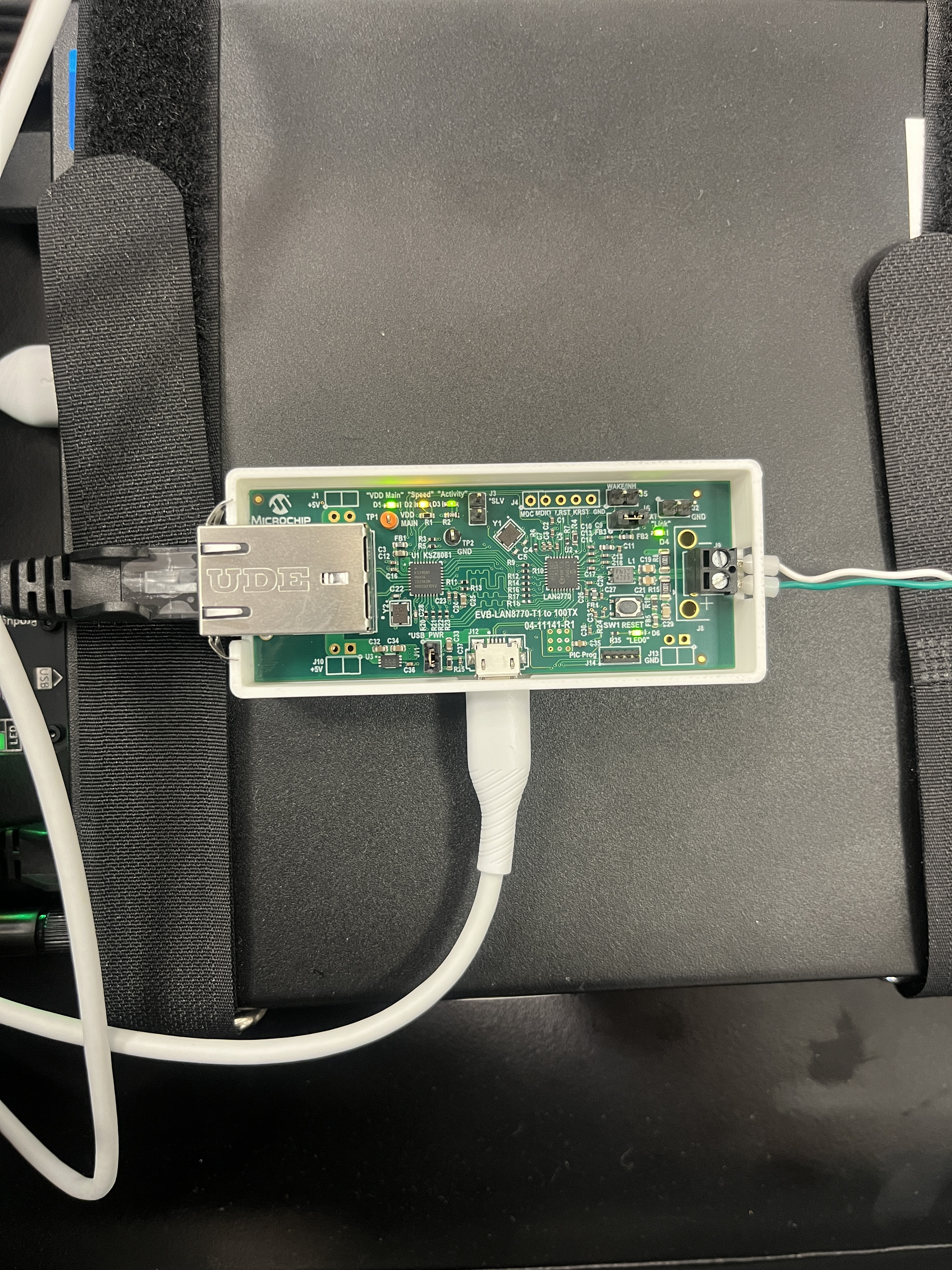
If your smart cart currently has a 3d printed box and T1 Adapter board like pictured below, and you’ve troubleshooted to this piece of hardware being broken, this document gives guidance on how to replace the unit.
Confirm that the T1 adapter board is bad: see Ping_devices not Seeing Aircraft or Droid
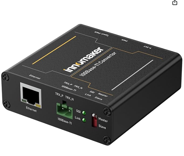
All smart carts built from the production line now use an Innomaker T1 converter. When the older T1 adapter breaks, please service the smart cart by replacing the unit with this model.
Required Materials:
Section titled “Required Materials:”- T1 Converter:
- Power supply:
- T1 ethernet wire harness (with connectors already fashioned; request these from inventory)
- 24AWG Ferrules
- 24AWG-compatible crimping tool
- VHB Tape for securing in the cart.
Instructions:
Section titled “Instructions:”- Remove the power connector for the T1 adapter from the NEO. This should be the USB-A side.
- Remove the RJ-45 ethernet connector from the T1 adapter board. Leave the ethernet wire connected to the NEO.
- Confirm that the Zip/Droid connector on the other end of the twisted pair is disconnected.
- Remove the twisted pair from the T1 adapter.
- If this twisted pair looks damaged (or you need a different length) cut a new one.
- Strip and crimp ferrules onto the wire ends.
- Take the 2pin molex connector on the Innomaker and place the crimped green wire on the twisted pair on the TRX_P side, and the white wire on the TRX_N side. Reconnect to the Innomaker.
- Make sure the Innomaker configuration is switched to “master”.
- Using VHB, secure the Innomaker near the NEO such that the ethernet RJ-45 Connector can reach the Innomaker and power supply can reach the power strip.
- Connect the power supply to the Innomaker and the power strip.
- Ensure the power led and link led lights are on.
- Confirm connection with an aircraft or droid with
ping_devices. If you see all the nodes. The swap is complete.
Did this guide help you get unblocked?
Open suggestions
There are no open suggestions.
Open pull requests
There are no open pull requests.