

Lock Mechanism -- Cam Hang Validator / Failure to Unlock / Failure to Lock
Applicable alarms (1)
Likely outcomes — click to expand
Based on 54 missions where this alarm fired in the last 90 days as of 2026-10-13
Grounding vs discrepancy (of 89 ZERP issues filed on these missions)
Top work orders
- Lock Mech Inspection · INSPECTION 29
- EV2/EV3 Perform Preflight Without Motors · INSPECTION 17
- EV2/EV3 Diagnostics Test Without Motors · INSPECTION 13
- Reset Droid after DLB · REPAIR 12
- EV2: Replace Lock Mechanism on Aircraft Docking Fin/Winch Assembly · MAINTENANCE_ACTION 12
Frequently replaced parts
| Part | P/N | Removals |
|---|---|---|
| DOCKING FIN WINCH ASSY, ZIP, P2 | 24084 | 110 |
| LOCK MECH ASSY, PRE-EV2, ZIP, P2 | 30166 | 65 |
| ASSY, SPOOL AND LINE, DOCKING FIN | 48477 | 34 |
| DOCKING FIN WINCH LRU, AIRCRAFT, P2 | 48561 | 27 |
| WINCH, ASSY, ZIP, P2 | 24078 | 24 |
Frequently co-occurring alarms (% of the 54 missions above)
Aggregated from fleet operations and refreshed daily. Individual outcomes may vary by site and configuration.
Background
Section titled “Background”This SOP is the resolution path for a few different conditions with the Lock Mechanism in the Docking Fin/Winch LRU
- the LOCK_MECH_STUCK alarm is automated software detection for a failure of the lock mech sensor’s state to move through the progression UNLATCHED → UNKNOWN → LOCKED within a specified time window after the GNC-commanded latching pulse. This catches the broad range of causes for Cam Hang (explained below)
- the Cam Hang Validator is a post-mission validator that is triggered in a similar way to the LOCK_MECH_STUCK alarm. But because it has a slightly different algorithm, they may catch different cases. Also targeted to catch the full range of Cam Hang causes.
- the Plunger Stop Validator is a post-mission validator that catches trends in the Cam travel within the lock mechanism. These trends are an indicator that the press fit of the Plunger Stop into the base of the Plunger is backing out.
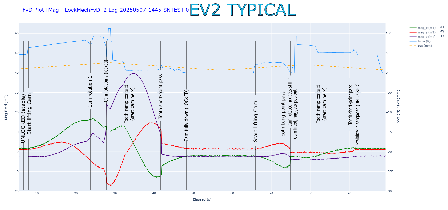
What is “Cam Hang?” During a lock or unlock cycle, the cam is lifted, rotated slightly by internal features, then lowered again into the next mechanical phase, similar to the internal workings of a click-click ballpoint pen. If the cam hangs in the partially-lifted position (usually after the lifting rotation, and usually in the locking cycle), then it is not ready to advance again when the winch next pulls up on it. This results in a failed unlock cycle and a stuck Droid. If the hang happens before rotation, the Droid is not secure and can fall out of the Aircraft under shock/vibe loads. This may result in a paraland event.
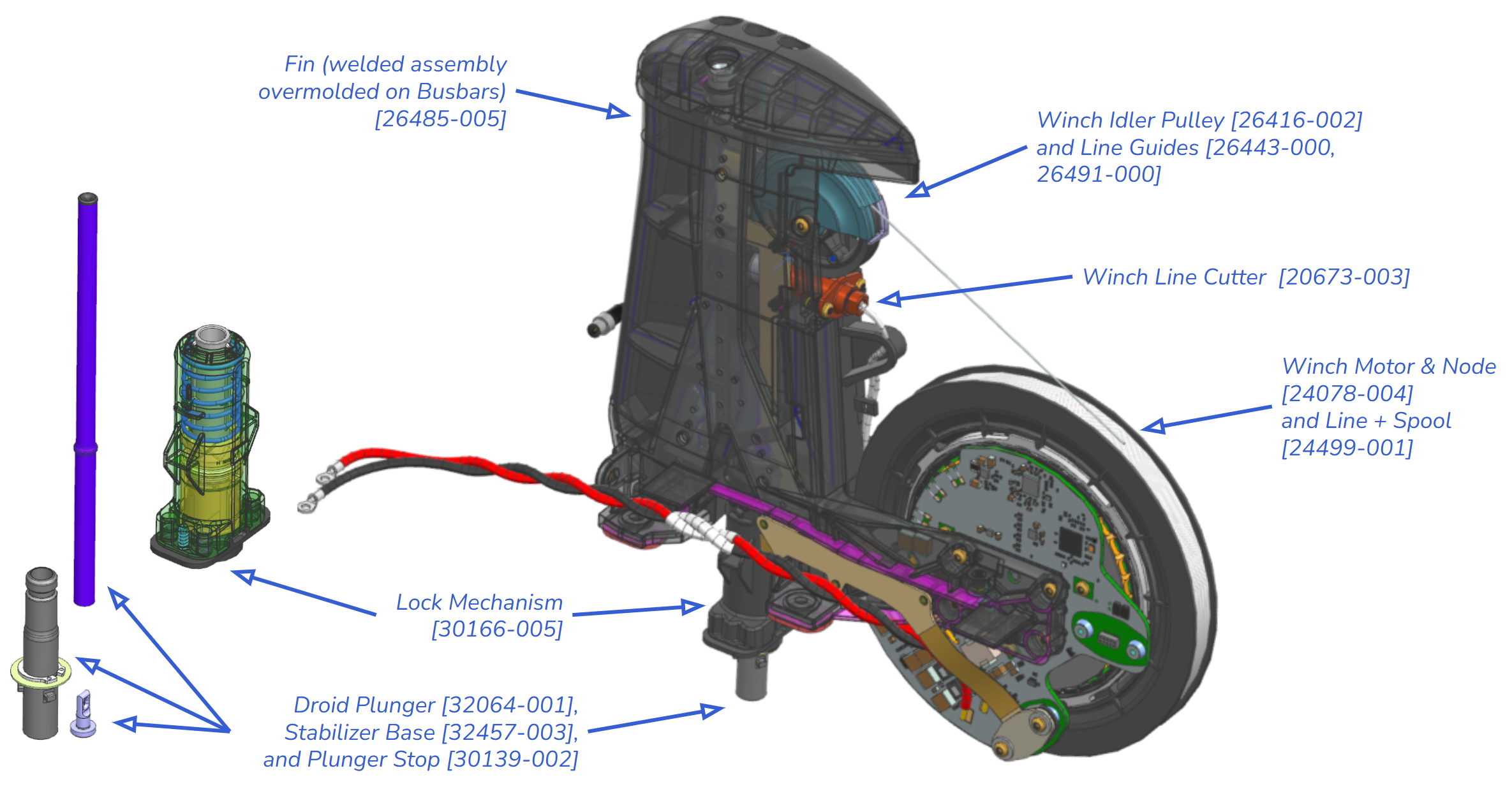
Part reference:
Phases of mechanism operation (from Force-vs-Displacement Tester – but can be keyed into log plot data based on 3 phases of the lock_mech sensor) (source png plotly)
Troubleshooting Steps
Section titled “Troubleshooting Steps”Step 1: Check for flex circuit failure
Section titled “Step 1: Check for flex circuit failure”If the Docking Fin flex pcba is damaged, the sensor for the lock mechanism may not be reporting actionable values to the winch, in which case there is likely no problem with the mechanical hardware. Usually this flex gets damaged about 3cm from the connector to the winch pcba where there is an abrupt edge on the flex stiffener. Damage can be identified either visually (breaks or tears) or by log investigation using this LogPlots template applied to the pertinent mission/flight/asset and time span. In the case of log review, a plot that satisfies the following two conditions is an indicator of a failed flex pcba:
- lock_mech.lock_mech_state (3rd plot) has a value of “UNKNOWN” reported for a > duration of at least one second.
- during the duration of the “UNKNOWN” in (1), there are NO value reported on the 2nd plot where the triad of lock_mech.b_lock_mech.x, lock_mech.b_lock_mech.y, and lock_mech.b_lock_mech.z should be.
Step 2: Inspect the plunger tube straightness
Section titled “Step 2: Inspect the plunger tube straightness”If the plunger is not axially-aligned to the tip of the stabilizer tube, it can jam in the long constraint of the lock mechanism and prevent the internal components from moving smoothly through the click-click cycle.
- With the stabilizer assembly (and Droid) lowered from the Aircraft, and with some slack in the winch line, spin the plunger (tallest portion of the stabilizer assembly) in the stabilizer base (part that anchors into the Droid Lid).
Step 3: Inspect the Plunger Stop press fit
Section titled “Step 3: Inspect the Plunger Stop press fit”If the Plunger Stop starts to back out of its pressed fit into the bottom of the plunger, it changes the Z-height sequencing of the lock mech internals and eventually the lock mech will fail to lock. This flaw will not prevent unlocking. With the stabilizer assembly lowered from the Aircraft and removed from the Droid lid, and with some slack in the winch line, compress the plunger into the stabilizer base and inspect the Plunger Stop on the bottom.
Step 4: Inspect the plunger telescopic motion (WIP)
Section titled “Step 4: Inspect the plunger telescopic motion (WIP)”Inspect:
- Plunger stop knot tail.
- Stabilizer assembly for debris.
If the plunger - stabilizer base sliding fit does not move freely, it can prevent the internal components of the lock mechanism from moving smoothly through the click-click cycle.
Step 5: Inspect the winch spool for line dig
Section titled “Step 5: Inspect the winch spool for line dig”“Line Dig” is a term for the most recent high-tension wraps of line on the spool “digging” their way down into the pile of looser wraps already present on the spool. It is rare except on new spools that have not yet completed a “real” lower/raise cycle of a Droid from 100m altitude. Line dig can lead to poor lock mech function if it prevents sufficient relaxation of the line tension for the lock mech to progress through its click-click cycle.
- With the fin fairing removed from the Aircraft, inspect the spool for line dig. It may appear “braided” around the line as it departs the spool and heads for the idler pulley in the fin.
Step 6: Inspect the winch spool and motor for rub points
Section titled “Step 6: Inspect the winch spool and motor for rub points”Assembly interferences that increase drag on the winch motor can lead to poor lock mech function if it prevents sufficient relaxation of the line tension for the lock mech to progress through its click-click cycle.
- With the fin fairing removed from the Aircraft, rotate the spool and motor gently by hand for a full rotation while taking care not to cause a snarl with the line slack that is created. Listen and feel for interference between the spool or motor rotor and adjacent parts.
graph TD
    check-for-flex-circuit-failure["<small><b>Step 1</b></small><br/>Action: Check for flex circuit failure"]
    is-the-docking-fin-flex-connector-damag{"<small><b>Step 2</b></small><br/>Question: Is the Docking Fin Flex Connector Dam..."}
    document-the-docking-fin-flex-on-the-po["<small><b>Step 3</b></small><br/>Action: Document the Docking Fin Flex on the ..."]
    inspect-the-plunger-tube-straightness{"<small><b>Step 4</b></small><br/>Question: When the Plunger spins within the sta..."}
    document-the-plunger-runout-with-photos["<small><b>Step 5</b></small><br/>Action: Document the Plunger runout with phot..."]
    inspect-the-plunger-stop-press-fit{"<small><b>Step 6</b></small><br/>Question: Does the bottom face of the Plunger S..."}
    document-the-plunger-stop-status-with-p["<small><b>Step 7</b></small><br/>Action: Document the Plunger Stop status with..."]
    inspect-the-plunger-telescopic-motion{"<small><b>Step 8</b></small><br/>Question: With the stabilizer assembly lowered ..."}
    document-the-parts-status-with-photos["<small><b>Step 9</b></small><br/>Action: Document the parts' status with photo..."]
    inspect-the-winch-spool-for-line-dig{"<small><b>Step 10</b></small><br/>Question: Does the spool have line dig?"}
    document-the-line-dig-with-photos-and-o["<small><b>Step 11</b></small><br/>Action: Document the line dig with photos and..."]
    inspect-the-winch-spool-and-motor-for-r{"<small><b>Step 12</b></small><br/>Question: Is there rubbing?"}
    document-the-rubbing-with-photos-and-or["<small><b>Step 13</b></small><br/>Action: Document the rubbing with photos and ..."]
    is-this-the-first-instance-of-cam-hang{"<small><b>Step 14</b></small><br/>Question: Is this the first instance of cam han..."}
    test-in-an-mx-dock-or-with-a-smart-cart{"<small><b>Step 15</b></small><br/>Question: There is a chance it was a one-off fl..."}
    return-to-service-first-instance["<small><b>Step 16</b></small><br/>Action: return to service"]
    replace-the-entire-docking-fin-winch-lru["<small><b>Step 17</b></small><br/>Action: Replace the entire Docking Fin / Winc..."]
    reassemble-the-droid["<small><b>Step 18</b></small><br/>Action: Reassemble the Droid. Verify the prop..."]
    if-there-is-still-a-problem-escalate-to{{"<small><b>Step 19</b></small><br/>Escalation: If there is still a problem, escalate..."}}
    check-for-flex-circuit-failure --> is-the-docking-fin-flex-connector-damag
    is-the-docking-fin-flex-connector-damag -->|Yes| document-the-docking-fin-flex-on-the-po
    is-the-docking-fin-flex-connector-damag -->|No| inspect-the-plunger-tube-straightness
    inspect-the-plunger-tube-straightness -->|Yes| document-the-plunger-runout-with-photos
    inspect-the-plunger-tube-straightness -->|No| inspect-the-plunger-stop-press-fit
    inspect-the-plunger-stop-press-fit -->|Yes| document-the-plunger-stop-status-with-p
    inspect-the-plunger-stop-press-fit -->|No| inspect-the-plunger-telescopic-motion
    inspect-the-plunger-telescopic-motion -->|Yes| inspect-the-winch-spool-for-line-dig
    inspect-the-plunger-telescopic-motion -->|No| document-the-parts-status-with-photos
    inspect-the-winch-spool-for-line-dig -->|Yes| document-the-line-dig-with-photos-and-o
    inspect-the-winch-spool-for-line-dig -->|No| inspect-the-winch-spool-and-motor-for-r
    inspect-the-winch-spool-and-motor-for-r -->|Yes| document-the-rubbing-with-photos-and-or
    inspect-the-winch-spool-and-motor-for-r -->|No| is-this-the-first-instance-of-cam-hang
    document-the-rubbing-with-photos-and-or --> reassemble-the-droid
    is-this-the-first-instance-of-cam-hang -->|Yes| test-in-an-mx-dock-or-with-a-smart-cart
    is-this-the-first-instance-of-cam-hang -->|No| replace-the-entire-docking-fin-winch-lru
    test-in-an-mx-dock-or-with-a-smart-cart -->|Yes| return-to-service-first-instance
    test-in-an-mx-dock-or-with-a-smart-cart -->|No| replace-the-entire-docking-fin-winch-lru
    return-to-service-first-instance --> reassemble-the-droid
    replace-the-entire-docking-fin-winch-lru --> reassemble-the-droid
    reassemble-the-droid --> if-there-is-still-a-problem-escalate-to
    style check-for-flex-circuit-failure fill:#dcfce7,stroke:#22c55e,color:#14532d
    style is-the-docking-fin-flex-connector-damag fill:#dbeafe,stroke:#3b82f6,color:#1e3a5f
    style document-the-docking-fin-flex-on-the-po fill:#dcfce7,stroke:#22c55e,color:#14532d
    style inspect-the-plunger-tube-straightness fill:#dbeafe,stroke:#3b82f6,color:#1e3a5f
    style document-the-plunger-runout-with-photos fill:#dcfce7,stroke:#22c55e,color:#14532d
    style inspect-the-plunger-stop-press-fit fill:#dbeafe,stroke:#3b82f6,color:#1e3a5f
    style document-the-plunger-stop-status-with-p fill:#dcfce7,stroke:#22c55e,color:#14532d
    style inspect-the-plunger-telescopic-motion fill:#dbeafe,stroke:#3b82f6,color:#1e3a5f
    style document-the-parts-status-with-photos fill:#dcfce7,stroke:#22c55e,color:#14532d
    style inspect-the-winch-spool-for-line-dig fill:#dbeafe,stroke:#3b82f6,color:#1e3a5f
    style document-the-line-dig-with-photos-and-o fill:#dcfce7,stroke:#22c55e,color:#14532d
    style inspect-the-winch-spool-and-motor-for-r fill:#dbeafe,stroke:#3b82f6,color:#1e3a5f
    style document-the-rubbing-with-photos-and-or fill:#dcfce7,stroke:#22c55e,color:#14532d
    style is-this-the-first-instance-of-cam-hang fill:#dbeafe,stroke:#3b82f6,color:#1e3a5f
    style test-in-an-mx-dock-or-with-a-smart-cart fill:#dbeafe,stroke:#3b82f6,color:#1e3a5f
    style return-to-service-first-instance fill:#dcfce7,stroke:#22c55e,color:#14532d
    style replace-the-entire-docking-fin-winch-lru fill:#dcfce7,stroke:#22c55e,color:#14532d
    style reassemble-the-droid fill:#dcfce7,stroke:#22c55e,color:#14532d
    style if-there-is-still-a-problem-escalate-to fill:#fef3c7,stroke:#f59e0b,color:#78350f
Hover or focus a block to preview it. Select the block to keep the preview open.
Replace the Docking Fin/Winch LRU (24084-0xx) as per UMM.
Verify the proper lock mech operation with the new hardware using the Smart Cart "ZipDroidFitCheck" app (minimum 3 cycles).
- If it fails, restart this inspection list with the new hardware.
Return the Aircraft to service.
Return the decommissioned components to engineering at the Aviary/Roost.
Replace the stabilizer base assembly (PLUNGER ASSY, LOCK MECH, ZIP, P2 [32064-001] + STABILIZER BASE ASSY, LOCK MECH, ZIP, P2 [32457-003] + PLUNGER STOP, LOCK MECH, ZIP, P2 [30139-002]) as per UMM 32.3.2.c Install Winch Line.
Verify the proper lock mech operation with the new hardware using the Smart Cart "ZipDroidFitCheck" app (minimum 3 cycles).
- If it fails, restart this inspection list with the new hardware.
Return the Aircraft to service.
Return the decommissioned components to engineering at the Aviary/Roost.
Use the MX tool to extract the Plunger Stop from the plunger.
Inspect the knot on the Plunger Stop. If it has any loose loops, cut the line close to the plunger stop and retie the knot as per UMM Install Winch Line.
Use the MX tool to press the Plunger Stop back into the plunger.
Reassemble to Droid.
Verify the proper lock mech operation with the new hardware using the SmartCart "ZipDroidFitCheck" app (minimum 3 cycles).
Return the Aircraft to service.
Use the MX tool to extract the plunger stop from the plunger. While separating the parts, visually check whether the a portion of the winch line (the knot tail) was exposed and stuck between the ID of the stabilizer base and the OD of the plunger/plunger stop.
Cut the line close to the plunger stop.
Replace the plunger, stabilizer base, and plunger stop with new parts. Thread them onto the line and retie the knot as per UMM Install Winch Line.
Use the MX tool to press the plunger stop back into the plunger, paying special attention to get the entirety of the knot tail inside the plunger.
Reassemble the stabilizer assembly to the Droid.
Verify the proper lock mech operation with the new hardware using the SmartCart "ZipDroidFitCheck" app (minimum 3 cycles).
Return the Aircraft to service.
Manually unspool 5m (~15 wraps) of line to remove the tangled section.
Manually re-spool the line onto the spool while maintaining significant tension on the line so that it packs in tightly.
Perform a WFH delivery with no payload to get a full unspool/respool under the weight of an empty Droid.
Return the Aircraft to service.
Replace the docking fin/winch assembly.
Test in an MX dock or with a Smart Cart, performing a minimum of 3 consecutive raise/lower cycles with 5 Lbs of payload in the front of the Droid and the Zip at the docked attitude (flat undersides of the docking fin are level)
Did it pass the raise/lower cycles?
For aircraft that are on SW prior to 2025.36, tag the removed LRU as "DO NOT USE UNTIL 2025.36 RELEASE" and return it to spares. There is a very high probability that the HW will work fine after SW enhancements.
Verify the proper lock mech operation with the new hardware using the SmartCart "ZipDroidFitCheck" app (minimum 3 cycles).
Return the Aircraft to service.
Return the decommissioned docking fin/winch assembly to engineering at the Aviary/Roost.
Resolution note
This plaintext block is ready to paste into the Resolution Note field on the ZERP issue you're working. The permalink below gives engineering review access to the full step-by-step timeline including any back-navigation; share it if the case needs a deeper look.
Permalink:
Session is too large to fit in a URL. Use Download session JSON to share the timeline out-of-band.
Did this guide help you get unblocked?
Open suggestions
Open pull requests
There are no open pull requests.